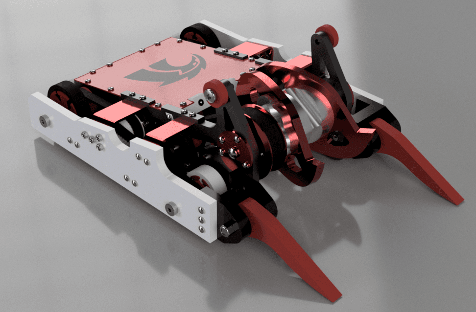
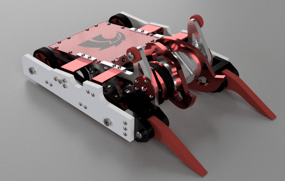
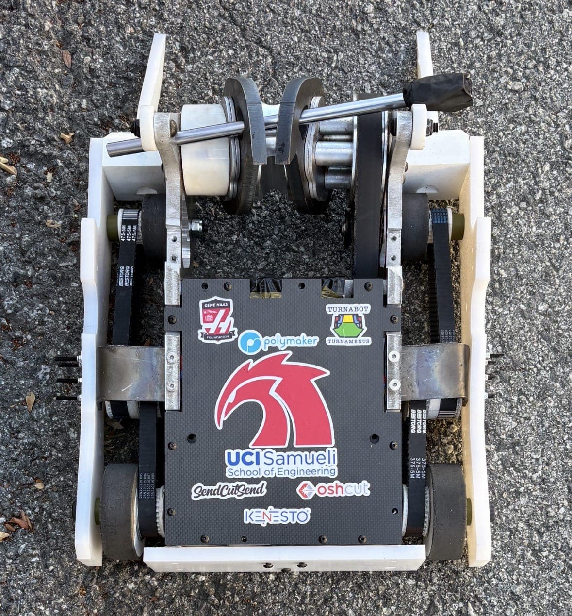


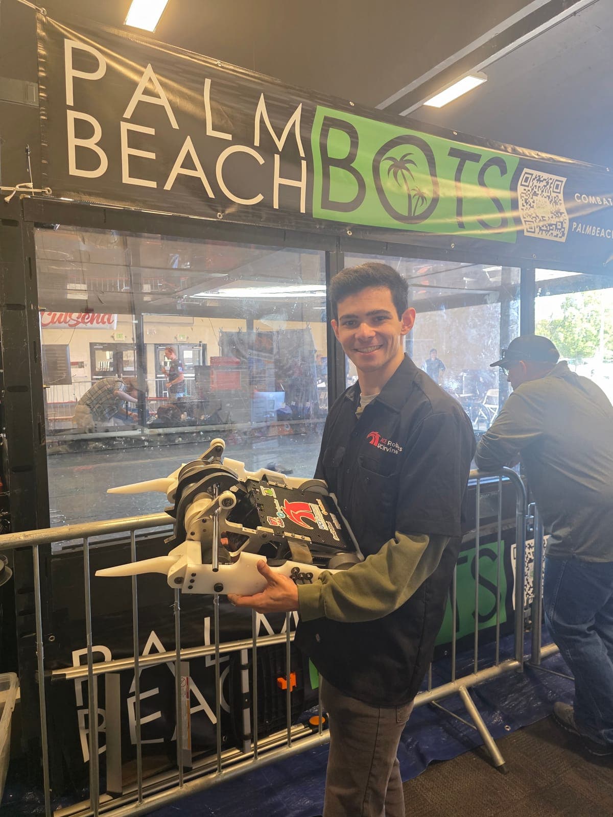


vs Professor Wasp
The drivetrain pulleys were not strong enough (they needed epoxy), and the weapon rods failed.
[KADEN: match 1 failure-and-fix write-up: what broke and why, the fix between matches, and how it held up in match 2]
30lb Combat Robot
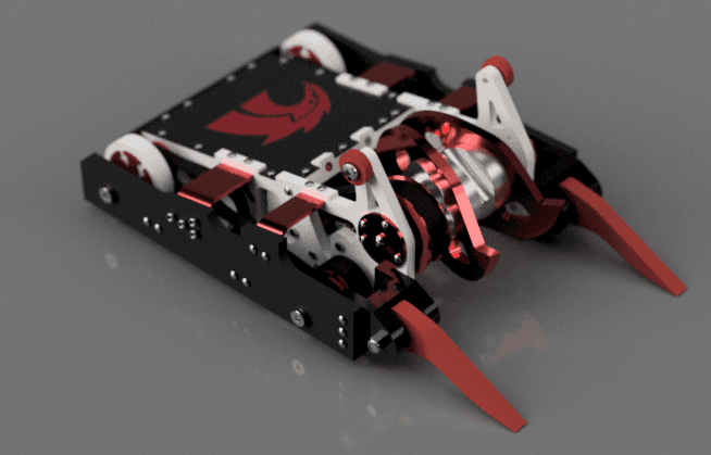
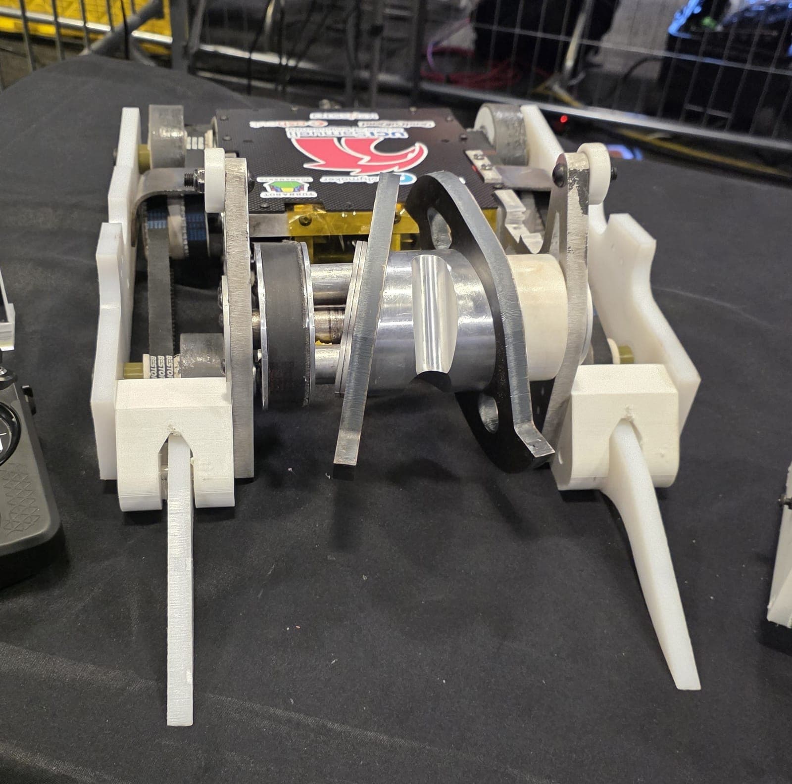

Drive values are predicted from my drivetrain model below.
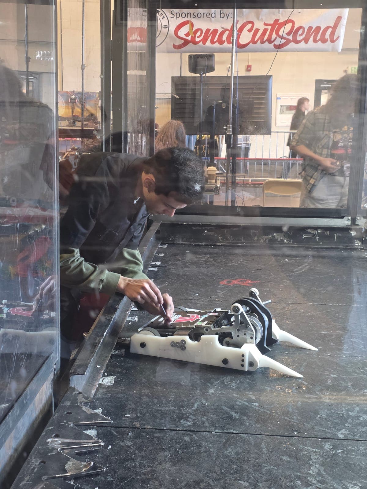
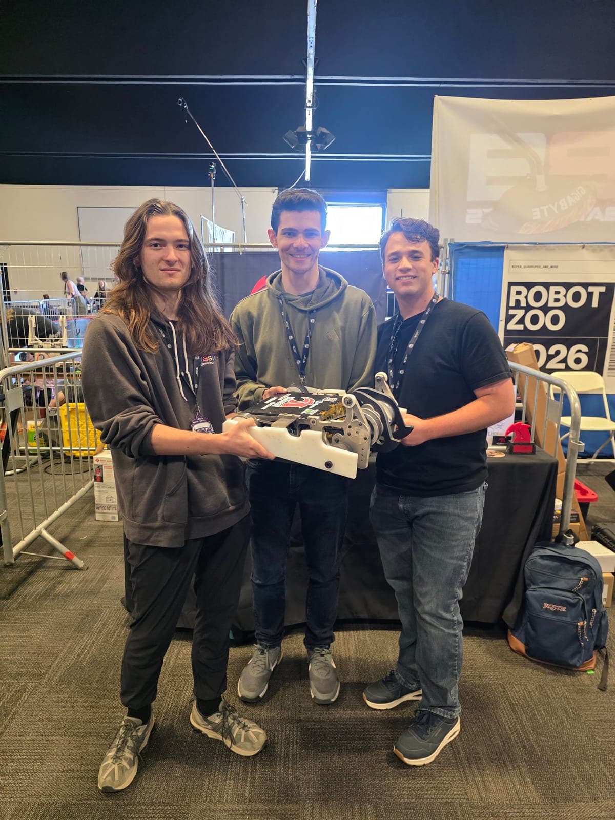
Combat robotics (think BattleBots) puts two remote-controlled robots in an arena, and the goal is to destroy the other robot. Robots compete in weight classes: 1 lb, 3 lb, 12 lb, 30 lb, 250 lb and others. If both robots survive the match, judges decide it, usually on damage (3 points), aggression (2) and control (2). The exact points change between competitions, but that split is typical.
Shear Force is a 30 lb robot built by Anteater Combat Engineering (ACE) Robotics at UCI. We started at the beginning of the Winter 2026 quarter, on January 12, and aimed at SCAR's "Carnage at the Cube" on April 24 to 26, 2026: sixteen weeks for UCI's first 30 lb robot, with a new weapon design, an angular drisk.
An eight-person team got the robot to a competition-ready state, with a large share of the work from me. At 2 am on the day we were due to compete, during a final test, the weapon ESC caught fire, and we did not compete. The root cause analysis is further down.
For the summer the team shrank to three: Jake, Matthew and me. I took over most of the work, debugging, fixing and improving the robot so it could compete at Open Sauce 2026, while working a full-time internship.
Shear Force was my first combat robot, and my role changed more than I expected: I started on chassis support and ended up leading the robot. I designed chassis parts, wrote the drivetrain model, ran the weapon CFD and FEA, helped manufacture and test, built the telemetry app, took over electrical after the fire and ran the timeline and sourcing for Open Sauce. The steps are below.
Winter 2026
Designed the first fork design and parts of the armour and chassis, working with Jake.
Winter 2026
Derived the 4WD model from first principles and built the simulator that set wheel sizes and pulley ratios.
Winter 2026
Ansys CFD to check the weapon could reach about 240 mph under the 250 mph limit; FEA to check it would stay retained axially.
Winter to Spring 2026
Helped source parts, plasma-cut the titanium, assemble and test the robot.
Spring 2026
Streamed ESC telemetry over an ESP32 to check the drivetrain predictions.
April 2026
The weapon ESC caught fire on the day of SCAR. We did not compete.
Summer 2026
Root cause analysis, wiring diagram, soldering and packaging; replaced the third-party telemetry program with SF_Telem.
Summer 2026 on
Timeline and sourcing to get the robot to Open Sauce, and the fixes after it.
Start of the Winter quarter, eight-person team
Fit, drive and inversion tests
Side armour supports made in-house
First weapon ESC stops working, no fire
Did not compete at Carnage at the Cube
Team of three; new electronics
Third ESC fails in the second session
San Francisco, two matches
Rods, hubs, moulds, red blades, weight check
TBD, likely December 2026
| Requirement | Target | Where it landed |
|---|---|---|
| Competition | ||
| Weight | ≤ 30 lb | The most important requirement. 29 lb 14 oz, under the 30 lb limit. |
| Weapon tip speed | < 250 mph | 244.67 mph predicted maximum |
| Safety inspection | Pass | Passed safety checks at Open Sauce 2026 (videos below) |
| Self-imposed | ||
| Drive top speed | 15+ mph | 15.51 mph predicted, 15 mph in 1.08 s |
| Torque curve | Reasonable | Traction-limited up to 9.65 mph on purpose, for pushing |
| Weapon tip speed | ~240 mph | 244.67 mph predicted |
The drivetrain of a combat robot is a game of tradeoffs.
Torque vs. Top Speed: Pulley ratio choices define the machine's personality. A higher reduction provides the torque necessary for pushing matches but sacrifices top-end speed. Conversely, less reduction enables high-speed maneuverability at the cost of raw pushing power.
Wheel Size vs. Positioning: With the inherent nature of the weight distribution (shifted forward due to the weapon) and the need for armor/forks, there is a critical tradeoff between wheel size and placement. Smaller wheels allow for a more forward drive axis to improve turning geometry, though they inherently limit top speed. Larger rear wheels are utilized to ensure the bot is invertible, capable of driving even if flipped.
Our team developed an innovative 4WD system where the front and rear wheels are mathematically synchronized via specific pulley ratios and sizing. This enables a larger rear wheel and smaller front wheel to maintain identical tangential velocity. This configuration maximizes top speed while maintaining the 4WD traction required to utilize torque where the shifting weight distribution demands it most.
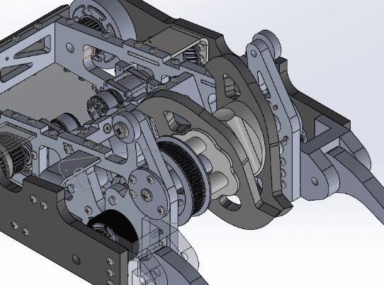
 Drivetrain System Prelim CAD
Drivetrain Derivations
While typical 4WD models are common, the uniqueness of this drive system required deriving the dynamics from first principles to validate motor curve performance. The full derivations are shown in the embedded pdf on the left.
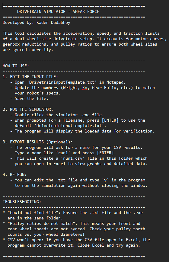
I converted these derivations into a standalone .exe tool. Users can input parameters via a .txt file to simulate performance and export data to .xlsx files. The software includes safety logic to warn if input ratios will cause velocity mismatch and subsequent wheel slip.
Using software iteration, we finalized a 2.5in front wheel and 3.5in rear wheel. To reduce complexity, the motor shaft pulleys were kept at 30 teeth for both. The front utilizes a 20-tooth wheel pulley while the rear uses a 28-tooth pulley to achieve synchronization.
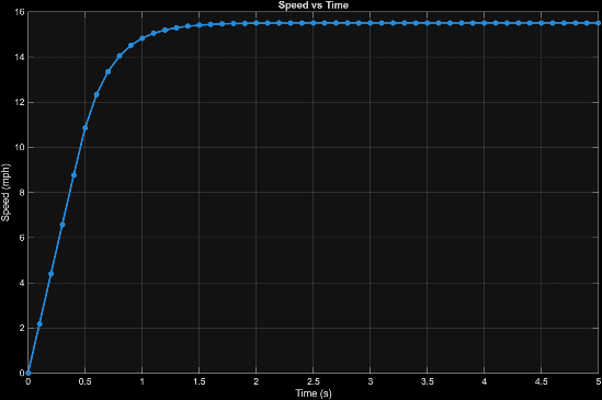
The result is a theoretical top speed of 15.51 mph, reaching 15 mph in 1.08 seconds. We are traction limited up to 9.65 mph, providing a built-in factor of safety for maximum pushing power at low speeds. We further limit ESC amperage to ensure full-throttle inputs don't cause unnecessary slip.
V1 answers one question: which wheel sizes and pulley ratios give the front and rear wheels the same surface speed. V2 is updated logic I built into SF_Telem, my telemetry app on Cosmic (my own game engine), to answer a harder one.
I wanted to try other pulley ratios for more torque or more speed. The parts I have fix the axle heights, and I cannot mount the wheels differently on the chassis. So a new ratio also needs new wheel diameters that keep both wheels at the same tangential speed and lift the chassis the same distance off the ground. Only discrete combinations satisfy both, and they are rarely round numbers. V2 searches for them: a feasibility solver and a wheel-diameter sweep.
I never built a V2 configuration, for cost reasons. The solutions exist, and I can use them if the drivetrain changes.
Takeaway With fixed axle heights, a gearing change is a constrained search over wheel diameters, not a single calculation.

An angular drisk is a fairly novel weapon system for combat robots. Our specification for the weapon’s top tip speed was approximately 240 mph, keeping the design comfortably under the 250 mph SCAR limit. However, a geometry spinning at these speeds is notoriously difficult to model due to complex vortices and the uncommon "drisk" shape.
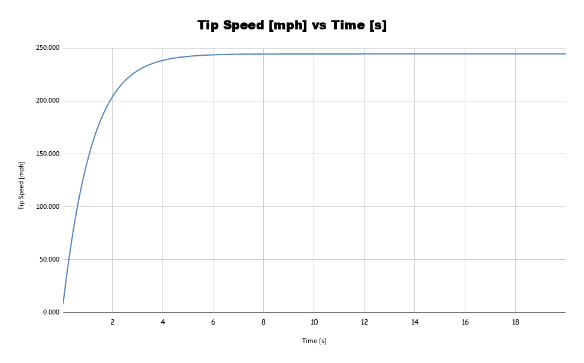
The primary goal of this CFD was to determine the parasitic aerodynamic torque induced on the weapon at various RPMs. This data allowed for a full system analysis, factoring in pulley ratios and motor curves to calculate the actual top tip speed and other relevant metrics, such as the time to reach 90% max tip speed.
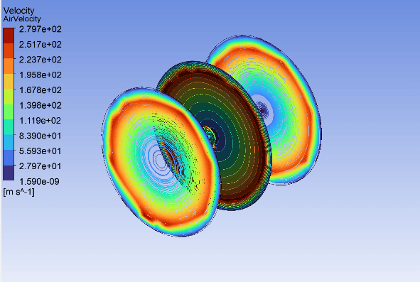
The CFD was conducted in Ansys Fluent using a Rotating Reference Frame (RRF) approach. I utilized the SST k-omega turbulence model to accurately capture boundary layer separation and wake effects at high rotational velocities. Additionally, while performing the analysis, I monitored the residuals to ensure they remained small, typically less than 10⁻³.
By simulating a range of RPMs, I obtained the necessary data to generate a drag torque vs. angular velocity curve. This represents the parasitic "air braking" force the weapon must override due to aerodynamic effects.
Similar to a drivetrain system, analysis can be performed to find the RPM of the weapon blades and the tangential tip speed velocity. The key difference between the weapon system and the drivetrain is that the aerodynamic effects of rotation are significant.
In a drivetrain system, top speed occurs near the motor's no-load speed. For the weapon system, however, the top speed occurs when the torque the motor produces is equal to the parasitic torque caused by the aerodynamics at that RPM.
The analysis involves calculating the weapon axle’s τ-ω curve (the motor’s curve multiplied by reduction and a loss factor). By subtracting the parasitic torque from the motor torque, the net torque is used to calculate angular acceleration via the weapon's inertia.
As expected, the angular velocity and tip speed behave like a first-order system:V(t) = C₁ (1 - e-C₂t). To verify the simulation, I graphed the torque vs. ω for both the weapon system and the absolute value of the parasitic torque. Top speed occurs where the two curves overlap. Note that this model does not account for voltage sag or other frictional components.
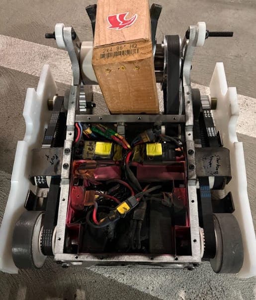
Before cutting metal we printed the whole robot. The prototype let us check that the CAD fit in real life, run early drive tests with telemetry, confirm the robot drives when inverted, and sanity-check the electronics and my drivetrain calculations.
Outsourcing the titanium side armour supports was too expensive, so we made them ourselves: plasma-cut from Ti-6Al-4V plate, then ground to clean up the edges.
The 7075-T6 aluminium parts were laser cut, and a vendor CNC-machined the weapon hubs.
Takeaway Making the titanium supports ourselves replaced a quote we could not afford, and printing the whole robot first let us test fit and driving before any metal was cut.
I started SF_Telem to check my drivetrain calculations against real data. The ESCs run AM32 firmware and send a telemetry frame from a serial TX pin: voltage, current, eRPM and temperature. From eRPM I get motor rpm, and from the ratios and geometry, wheel speed and weapon tip speed.
My first setup streamed the ESP32 output to the Arduino serial monitor, where I copied numbers by hand. A third-party app (Serial Studio) was the next step, and it was buggy. So I wrote my own.
The ESP32 reads the ESC's UART frames and forwards them over Bluetooth. Pairing with it opens a COM port on my PC; SF_Telem reads the packets from that port and plots them with ImGui and ImPlot, which I built into Cosmic for this app and have used for other Cosmic work since.
I can load scripts that make the ESP32 send dummy data, read the raw hex packets in a sniffer to see whether anything is arriving, and debug the weapon or the drive on its own.
The videos are no-load motor tests I ran before installing the motors, some on older versions of the app with fewer plots. The same app recorded the weapon ESC data that the root cause analysis below depends on.
Takeaway Owning the whole path, from ESP32 firmware to plots, turned an unreliable serial stream into data I could use to diagnose a failure.

At 2 am on the day of SCAR, during a final test, the weapon ESC caught fire. Our first diagnosis: the weapon bearings had gone in without grease, flattened and marked the shaft. The weapon stalled, the motor kept demanding current, and the ESC had no protection fast enough to stop it. Problem solved, or so it looked.
Flattened, ungreased bearings, the marked shaft and the burnt ESC
It was not the whole story. In desert testing, earlier in the spring, the same model of ESC had stopped working after about five runs, with no fire and no stall. It still connected to the AM32 configurator but would not take new settings. We put it down to dust or a cold joint and had no time to look further.
In summer testing, with new electronics, new greased bearings and a weapon balanced on a jig, a third ESC failed the same way: no stall, no fire, it stopped and would not take settings. This time I had SF_Telem on the weapon ESC, so I ran a proper root cause analysis.
| ESC | What happened | Settings | Data |
|---|---|---|---|
| Desert ESC | Desert testing, spring 2026. Stopped after about 5 runs; no fire. Connects to AM32 but cannot be flashed. | Stall protection off | No telemetry |
| Fire ESC | Final test, day of SCAR. Weapon stalled on flat bearings; fire. | Current limit 100 A; stall protection probably off | No telemetry |
| Jake ESC | Second SF_Telem session, July 2026. Failed without a stall; the 200 A fuse did not trip; telemetry flat-lined. | Stall protection on; startup power 110 %; current limit 160 A; temp limit 120 °C | Last readings 52 to 57 °C, 59 A, voltage reading bogus |
Before the Jake ESC failed, SF_Telem logged: first session (June 28), 39.6 A peak, 21 to 39 °C, 13,966 motor rpm; second session, first run, 126 A, 172 mph tip speed, about 29,000 rpm; a quick spin-up, 184.3 A, 30 to 42 °C, 31,100 rpm, 181.7 mph. Tip speed is calculated from eRPM and the geometry; there is no sensor on the blade.
Peak 188.3 A at 48.5 s, log time 11.7 to 57.7 s. Use the arrow keys to read values.
Peak 182.7 mph at 46.8 s, log time 11.7 to 57.7 s. Use the arrow keys to read values.
Peak 142.1 A at 38.2 s, log time 11.7 to 78.0 s. Use the arrow keys to read values.
Peak 57 °C at 47.0 s, log time 11.7 to 78.0 s. Use the arrow keys to read values.
Minimum 34.3 V at 37.7 s, log time 11.7 to 78.0 s. Use the arrow keys to read values.
SF_Telem CSV, 60 Hz, resampled to 10 Hz for the web, corrupted packets (impossible voltage or rpm) removed. Peak figures in the text are the values SF_Telem reported for each run.
The numbers are for the weapon motor, a TP-5660 at 950 KV (212 A maximum, 0.0049 Ω winding resistance), on 12S (50.4 V fully charged). Nothing actually reaches 10 kA; the MOSFETs fail first. The number shows that in a stall the only thing limiting current is the motor's winding resistance.
Start-up has the same ω = 0 condition, but the ESC ramps the duty cycle (effective voltage = duty × 50.4 V, switched at about 48 kHz) so back-EMF builds before current runs away. Software current limiting measures current through shunt resistors, compares it with the limit and lowers the duty cycle, in a loop. Stall protection waits for a de-sync. Both respond in milliseconds; stall current rises in microseconds. A normal stop is safe because the throttle is already at 0 %.
I opened all three ESCs. The two that stopped working are each missing a resistor, which may never have been fitted; I found no debris or other damage. My theory for those two is a temperature-related failure around 50 °C, which would be low for this ESC. Every failure came after several runs in a session, never on the first.
I stopped trying to explain the Sequre ESC (SQESC 12200, rated 200 A continuous and 250 A peak) and replaced it with a Hobbywing ESC. It weighs about 0.5 lb against about 0.2 lb, so I repackaged the electronics to fit it within weight. Its own telemetry read around 350 A on hits at Open Sauce, above the Sequre's peak rating. I have had no ESC failures since.
The data points to an ESC that is under-rated for this weapon's current spikes, at start-up and possibly under braking, but I cannot say exactly why two of them died without a stall, and that still bothers me.
Takeaway Firmware current limiting cannot protect against a stall; the protection has to be mechanical or in hardware, and logging the weapon ESC is what turned guesses into an analysis.
By this point I had taken over all of the robot's electrical work.
Takeaway Generating the diagram from code means it changes when the wiring does, and the next person can wire the robot without me.
July 17 to 19, San Francisco
Getting to Open Sauce took the whole summer: three of us rebuilt the electronics, replaced the weapon ESC and fixed what testing broke, and I did my part around a full-time internship.
The drivetrain pulleys were not strong enough (they needed epoxy), and the weapon rods failed.
Shear Force lost; the battery was punctured.
Takeaway The replacement weapon ESC held through both matches; what failed this time was mechanical (weapon rods, drive pulleys) and a punctured battery.
Takeaway Open Sauce showed where the robot breaks; this list is the response, and the September weigh-in is where it stands.
I ran a static structural FEA in Ansys to check that the weapon would stay retained axially.